Now that the hardware was done, I somehow needed to translate the tiny resistance change of the strain gauges into something that the computer could understand, and then send it to the computer. There are a few different components of this:
I made the Arduino and Bluetooth module easily removable from the rest of the circuitry so that I could use them in other projects if I wanted. Everything else is soldered around a little bit of circuit board.
Each of these components will get its own section, so you can learn more about them below.
- A simple circuit called a “Wheatstone Bridge” which takes the small resistance change from the strain guages and turns it into a small voltage change.
- An Arduino Microcontroller which acts as the central brain, reading information and sending it to the computer. An Arduino is a really small, cheap, low processing power computer that can run simple programs and is easy to interface with hardware.
- A voltage amplifier and analog-to-digital converter acting as the middlewoman in between the Wheatstone Bridge and the Arduino. It takes the tiny voltage change, boosts this into a moderately sized voltage change, and digitizes it into a binary number of 0’s and 1’s that the computer can understand. I used a HX711 board that was designed for this purpose.
- A Bluetooth dongle, which the Arduino can use to send information to the computer.
I made the Arduino and Bluetooth module easily removable from the rest of the circuitry so that I could use them in other projects if I wanted. Everything else is soldered around a little bit of circuit board.
Each of these components will get its own section, so you can learn more about them below.
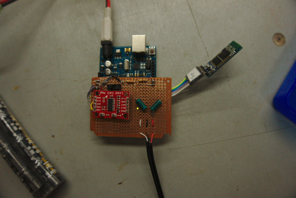
Above is a picture of all the circuitry. The red rectangle is the HX711 Load Cell Amplifier Breakout Board from Sparkfun. The two smaller green cylinders are two of the resistors of the Wheatstone bridge. The other two resistors are the actual strain gauges on the force sensor, hooked up remotely. The dangly thing off right is the bluetooth antenna. The blue board underneath the brown board is the Arduino
Wheatstone bridge
If you read the page on theory then you should know how a Wheatstone Bridge works. I made one using some fancy resistors that were given to me by Jeff Steele, the Technical Director and resident lab genius of the Physics Department. Thanks Jeff! The resistors are fancy because they have a very precise, constant resistance that won’t add much noise to the resistance change signal coming from the strain gauges.
To connect the sensor to the circuit I used a standard 3mm headphone audio jack. This made it easy to connect and disconnect the circuit and the sensor from each other. At first I just used some cheap individual male-female jumper cables here for each individual lead, but that did not work: Whenever any of these connections was wiggled, the resistance within the connection would change enough to throw off the reading. When your “signal” comes from a few millohms of resistance change within the strain gauges, it is really easy for bad connections to introduce noise that covers up this signal. In fact, just putting your finger over the top of the gauges raises their temperature enough that their resistance changes, and the final reading is off by up to 10 pounds!
To further reduce contributions from noise, I made the wires and cables as short as possible so they would not act as antennas and pick up any of the stray electromagnetic noise that is generated by the millions of electronic devices with which we surround ourselves. As you can see, I was trying to be as careful about minimizing noise as possible. The signal from the strain gauges was very small in relation to all of the other things in the circuit which could possibly change their resistance.
HX711 Amplifier and ADC
I bought this board online for about $15. It was designed specifically for interfacing between a load sensor/wheatstone bridge and an Arduino, so it was really easy to use. Plug in a few cables into the bridge, plug a few more into the Arduino, and we’re pretty much good to go.
The analog-to-digital converter (ADC) in the HX711 can sample the voltage at a rate of either 10 or 80 samples-per-second. Since I wanted to be able to drop weights onto climbing equipment and be able to measure the forces during those sudden impacts, I wanted to be use the highest possible sample rate. To do this I had to scratch off a little trace of wire on the backside of the board which acted like a switch, which turned the board from 10SPS to 80SPS mode.
I was hesitant that even 80 SPS would be fast enough, since a climbing fall can be over within a quarter of a second, and I was partially right. When I did tests of a falling “climber” onto a stretchy rope that simulated a lead fall, the ADC could keep up and the plot was a fairly smooth curve. However, when I tested a falling climber on a very static(non-stretchy) dyneema sling, the plot was a sudden peak and then flatline. The sling stopped the fall too fast, within 1/20th of a second, so I only got a few data points, and thus perhaps it missed the actual peak force that it took to broke the sling. Oh well, I might have to figure out some other method of ADC, but until then the HX711 works great!
Arduino Microcontroller
I used an Arduino Uno that I’ve had for a few years that I’ve used for various other projects. You write code for the Arduino on your computer, and then upload it to the Arduino using a USB cable. Then you can unplug the cable and the Arduino will just start running the program you wrote as soon as it gets power.
At first I powered it using either a wall plug and cable or USB cable to computer, but when I decided I wanted everything to be wireless I had to come up with something better. So I took an old airsoft gun battery that I had saved and soldered up a connection that would plug into the Arduino.
Now that the circuitry was complete, it was time to write the code to give our Arduino some brains, and then make a computer talk to the Arduino. Click here to move on to the post on software!
